Electrical Test Equipment For Substation & Protection Relay Testing
Products: Transformer Testing
The company has a wide range of portable transformer testing equipments that helps the commissioning and maintenance engineers to test and evaluate the characteristics of their transformers.
The instruments capable of testing all types of transformers like Power, Distribution, Voltage and Current transforms.
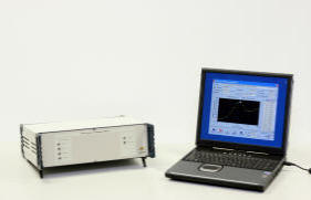
Transformer Turns Ratio Measurement unit.

The The measurement equipment ETP-1, is a unit that automatically performs the following measurements on all types of power, distribution or instrument transformers:
-
Actual turn ratio for each position of the tap changer.
-
No load current and power, at the test voltage.
-
Polarity and phase angle between voltages and voltage/current.
-
Automatically calculates results according with the connection group.
CHARACTERISTICS
The connection to the transformer taps is guided from the computer to avoid connection errors. Enables to select the number of the tap changer positions to be measured, as the software informs the position that should be measured each time.
For each tap changer position, a three phase automatic measurement is performed. It is not necessary to change the connection to the transformer taps.
The no load test current waveform is presented on the computer screen.
It detects possible problems
in the iron core.
The test time for each three phase test position is less than 10 seconds.
The measuring range has a ratio between 1:1 to 3000:1.
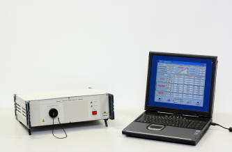
Recovery Voltage and Insulation Measuring Unit.

The transformers testing equipment ETP-2, is a unit that automatically performs the following measurements in all type of power, distribution, or instrument transformers:
-
Recovery Voltage of the insulation.
-
Insulation resistance.
-
Polarization Index.
To measure these parameters, the unit applies different levels of DC test voltage through an internal programmable automatic DC voltage supply.
The measured values are acquired automatically in the specified time.
The equipment evaluates the actual general status of the insulation, and detects possible ageing problems in the quality of the paper/oil insulation.
The recovery voltage test, designed for oil insulated transformers, is a new outstanding technology which allows advanced diagnostic of the paper insulation status and ageing, without considering the status of the insulation oil.
It is a
great advance, due to the fact that until now, there is no other method
to know the paper insulation status, without extracting it from the
inside of the transformer.
At the same time that the recovery voltage test occurs, the insulation
resistance test, the polarization index and the time constant test are
performed as well, delivering all the necessary complementary
information for a proper and accurate evaluation of the general
insulation status.
CHARACTERISTICS
-
Fully automatic Recovery voltage test in all the test cycles of voltage application, discharge of the insulation and measurement acquisition.
-
Automatic generation of graphic representation of the measured values on each test cycle .
-
Total test time of 40 minutes using the time base of 100 ms.
-
The connection to the transformer is guided from the computer to avoid connection errors.
-
All measurement processes are automatic.
-
Results values are automatically corrected to a reference temperature enabling, standard results.
-
Numerical and graphic presentation give the results of the following parameters:
-
Recovery Voltage.
-
Raising time of the capacity.
-
Insulation resistance.
-
Time constant.
-
Polarization Index.
The graphic curves gives very important information about the evolution of the obtained values, which makes the diagnostic of possible problems fast and easy.
-
-
The control program allows selecting the following possibilities to perform the insulation tests:
-
HV + LV against Ground.
-
HV against LV + Ground.
-
HV against LV + Tertiary + Ground.
-
Winding Resistance Measurement Unit.

The measurement equipment ETP-3, is a unit that automatically performs the following measurements in all type of power, distribution, or instrument transformers:
-
Winding resistance value in single or three phases.
-
Automatic correction of the resistance per phase to a predetermined reference temperature.
-
Automatic calculus of the compound winding resistance, for different configurations Delta, Star, etc,
CHARACTERISTICS
-
Performs the measurement of each phase, sequentially, without any change in the connection to the transformer, for each tap changer position.
-
Uses a four wire measuring method to avoid any error from the connection cables.
-
Automatic magnetization and de-magnetization of the iron core and this process assures the accuracy and the repeatability of the resistance measurements and also the safety of the operator and the measuring unit in case of a sudden disconnection of the test leads.
-
Auto range from 1mΩ to 1KΩ.
-
The test current range from 5mA to 20A is automatically selected.
-
Automatic calculus of the resistance per phase.
-
The measured value is not affected by temperature variation or/and changes in the test current.
-
High immunity to external interferences.
-
Extremely fast measurement cycle.
-
The connection to the transformer is guided from the computer to avoid connection errors.
-
All the measurement process is automatic.
-
All the result values are automatically corrected to a reference temperature value, to allow standard results along time.
Short Circuit Impedance Measuring Unit.

The measurement equipment ETP-4 is a unit that automatically performs the following measurements in all type of power, distribution, or instruments transformers:
-
Short circuit Impedance measurement.
-
Short circuit current at the test voltage.
-
Short circuit power loss.
From the information supplied by this test unit it is possible to have an idea about the physical integrity of the transformer under test. The typical problems that are easily detected with this unit are the following:
-
Physical displacement of the transformer windings, due to electromagnetic efforts.
-
Problems in the iron core.
-
Transport damages.
-
Fixation elements which may be broken.
The program obtains from the measured values the components of the impedance triangle in short circuit. From this information, and its evolution in time it is possible to determine which part of the transformer is being deteriorated.
CHARACTERISTICS
The software program guides the correct connection of the test cables on the primary winding and the short circuits that must be done in the secondary (or tertiary) side, according with the specific connection group the transformer under test has.
The software program recommends the tap changer positions that should be tested according with the maximum regulation % and the nominal tap.
Displays and records the current and voltage waveform, this improves the diagnostic capability for further analysis.


